Four-Bar Linkage Robot
As a part of the Machine Design course, I worked in a team of five to develop a four-bar linkage mechanism. On my own, I also attempted to develop a cam-actuated mechanism that would engage the extra scoring button.
Skills developed:
Kinematics design
Joint design
Mechanism development
Software utilized:
SolidWorks (CAD)
Arduino IDE
Tools put to use:
CNC mills (Tormach 770M)
Waterjet (Ward A-0612)
Fuse 1 Nylon SLS Printer
Hand tools
Selection of Kinematics
To select the linkage geometry, we utilized SolidWorks Block tool in order to efficinetly transfer the coupler linkage between the points. We then selected the geometry that maximized the score for the linkage (which in turn depended on the volume the linkage took up and on the angles of operation of the linkage) which was also able to travel to the scoring locations on the field.


Joint Design for 4-Bar Linkage
We then proceeded to select the hardware for the joints of the linkage. To ensure the smooth motion between the joints, we utilized a shoulder bolt that passed through a bushing press-fit into one of the linkages; we separated the links using the thrust bearings and washers, and fastened the bolt using a nylon-insert locknut, as illustrated. When needed, we also used precisely machined spacers to offset links from one another.


Hardware Development for 4-Bar Linkage
We also designed and manufactured the hardware components of the robot, such as the transmission system, the mounting hardware, the links, and the mechanical stops.


Attempt at Cam Mechanism
On my own time and effort, I also attempted to develop a cam-actuated mechanism that would actuate at the start of the robot’s motion through a release of a pre-loaded spring. While the system did work on its own, I made a significant conceptual mistake during the system integration stage: namely, the encoder resolution was not sufficient to get the linkage to reproducibly go into the correct position to press the button. Despite this, the mechanism design from the ground up and the electromechanical integration was a good learning experience.

Initial sketch of the mechanism layout


Driving sketch for main dimensions of the mechanism
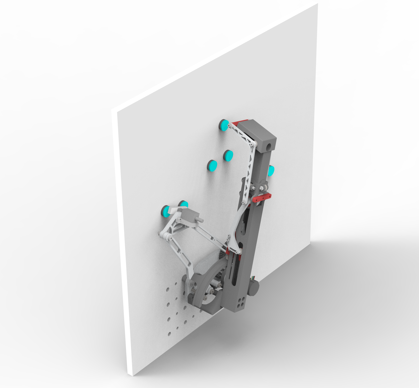
Full CAD of the arm

Functional prototype of the arm

CAD of robot with arm

Arm and 4-bar linkage integration in real life