Integration with Chassis
My contribution: suspension mounting hardware redesign and standardization, integration of suspension hardware with chassis geometry, jigging for welding.
I worked with Chassis to integrate suspension tabs into the design; I then developed standardized suspension hardware that utilized anti-dive slugs to enable adjustments of the z-coordinate of the suspension inboard points, and designed jigs for welding these and other tabs onto the chassis.
Skills developed:
Cross-system integration
Standardization
Jigging & fixturing
Software utilized:
SolidWorks (CAD, FEA)
Tools put to use:
3D-printers
Hand tools
The goals for suspension mounting hardware this year were to introduce adjustability into the system and standardize the components used for mounting suspension wishbones. We decided to accomplish both goals through the introduction of the anti-dive slugs, which are small inserts that allow for variation of z-coordinates of wishbones' mounting points, thereby allowing for fine-tuning of anti-dive and anti-squat effects.
To integrate these inserts into the system, I redesigned suspension wishbone-mounting tabs. On the previous car, we had two different designs of suspension tabs on front and rear; I chose to standardize to a single design in order to allow for consistent mounting and to utilize standardized components between front and rear of the chassis, as discussed below.


Old Front
poor manufacturing tolerances due to each mounting points having 2 tabs that both need to be welded at correct locations
non-standardize hardware, lots of unique components due to differently-spaced tabs
mounting points all at different angles

Old Rear
non-variable z-coordinates, suspension points are permanently fixed
standardized to AN6, had problems with clearances
rod ends are mounted horizontally, bearings are experiencing the largest forces in axial direction

New Design
introduced anti-dive lugs, enabling adjustments in z-coordinates of the mounting points
standardized to AN4, cut on weight and reduced the number of unique mounting components to 5 across all wishbone mounting points
rod ends are mounted vertically, bearings are experiencing the largestforces in radial direction, for which they are rated the highest
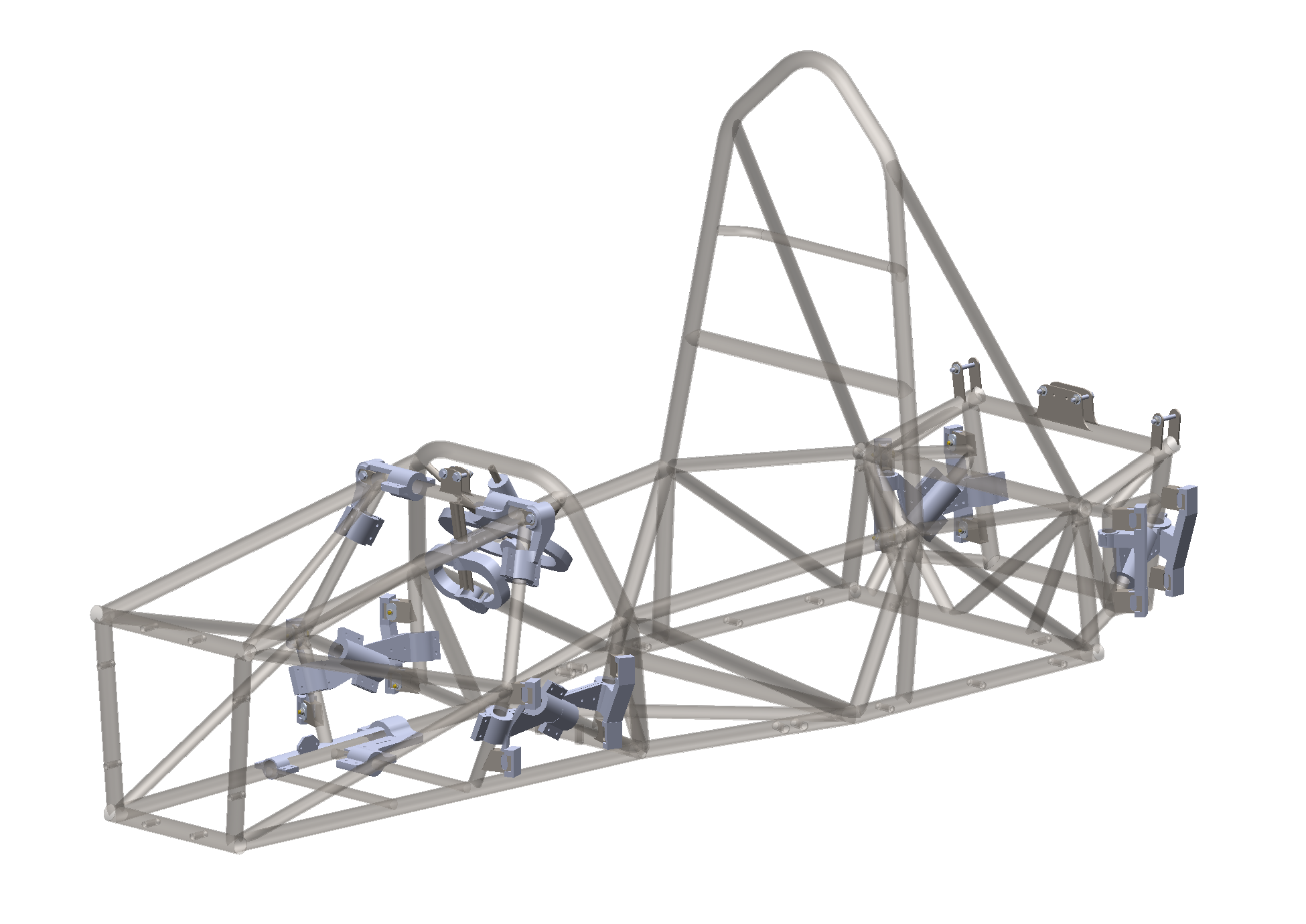
Because the tabs had to be changed in shape and had to be placed vertically to allow for fine-tuning of the z-coordinate, I worked with the Chassis Lead to find suitable locations for the tabs and to alter the triangulation of the chassis tubes in order to accommodate for the new shape of the tabs.


Following the integration with the chassis, I was able to develop the hardware for the new tab design. The standardized tab dimensions allowed for standardization in hardware, as well; I was able to cut the number of unique mounting components to 5 (including the tab), as seen on the image to the left.
I was also able to downsize the fasteners from AN6 (implemented on the previous year's rear tabs) to AN4. Furthermore, the new design allowed for vertical positioning of the rod-ends; the rod-end bearings are designed to withstand higher loads in radial directions, and the vertical mounting resulted in rod-end bearings experiencing the highest loads in the radial, and not axial, direction.
To ensure the reliability of the system I utilized SolidWorks' FEA capabilities; both the suspension tabs and anti-dive slugs had a minimum factor of safety of 1.3 at the maximum load case scenario, which confirmed the system to be reliable for use. I also selected the anti-dive slug to be out of a softer material (Aluminum 7075), while the tab had to be made out of 4130 Steel. I did so in order to ensure that if any wear occurs within the system, the anti-dive slug will wear out first: the slug is replaceable while the tab is rigidly welded to the chassis.


After I finalized the tab design, the team manufactured the tabs and prepared to outsource them for welding off-site, since we lack the facilities to be able to weld in-house.
In order to locate the tabs in their exact locations during welding, I designed and printed jigs that would orient the tabs on the correct spots on the chassis. All tabs vary from one another in their chassis-adjacent sections (because they are placed at different nodes of the chassis), therefore in order to communicate the correct placement of tabs I also designed a nomenclature and wrote a document on how to locate the tabs on the chassis.
I also designed and printed jigs for the steering column and steering rack, as shown in the pictures to the left.


Following welding, we assembled the suspension on the car. Here is how it looks like in real life.
